Deposit Processes
- Deposit processes are treated implicitly in water transport equations.
- First, deposition flux trends are evaluated for each variable before advection computations :\(Fl_{w2s}^a= W_s . f_2(\tau_s,\tau_d)\) (m/s)Then after advection resolution, effective deposit is computed with new concentrations in water (estimated after transport and settling)\(Fl_{w2s}^b= Fl_{w2s}^a*C_{bottom}\) (Masse/m2/s)and sediment layers are updated
The deposit management is differently treated in version 1 (Deposit Processes : Version 1) and version 2 (Deposit Processes : Version 2).
The porosity estimation is different which makes it possible, in version 2, not to make any more hypothesis on the volume concentration of deposit sediment (sorted or mixed in the version 1 with the variables cvolmaxsort or cvolmaxmel, respectively)
A sliding process of the fluid mud is taking into account (Sliding Processes)
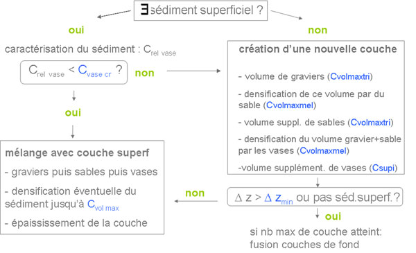
Deposit Processes : Version 1
- first deposit of gravels, then sands, then muds
- deposit is caracterised by the mass fraction of each variable ( \(f_{rdep}(iv)\) )
Deposit Processes : Version 2
Simultaneous deposition of gravel, sand and mud.
Deposits from bedload transport
- The divergence of the bedload fluxes is calculated in each mesh (i,j) in order to deduce the contribution of sediments (gravel, sand) resulting from transport by bedload (in kg) intervening in the adjacent meshes.
- This procedure for bedload is done with an explicit decentered upstream scheme., with two steps :
- a first sediment extraction step in the mesh (i,j) equal to the transport rate multiplied by the time step,
- then the calculation of the incoming mass in this same mesh coming from the fluxes at the level of the adjacent cells
- For each class concerned by bedload, the quantity of sediment entering a mesh (i,j) is taken into account by adding it to the deposition flux associated with the suspension.
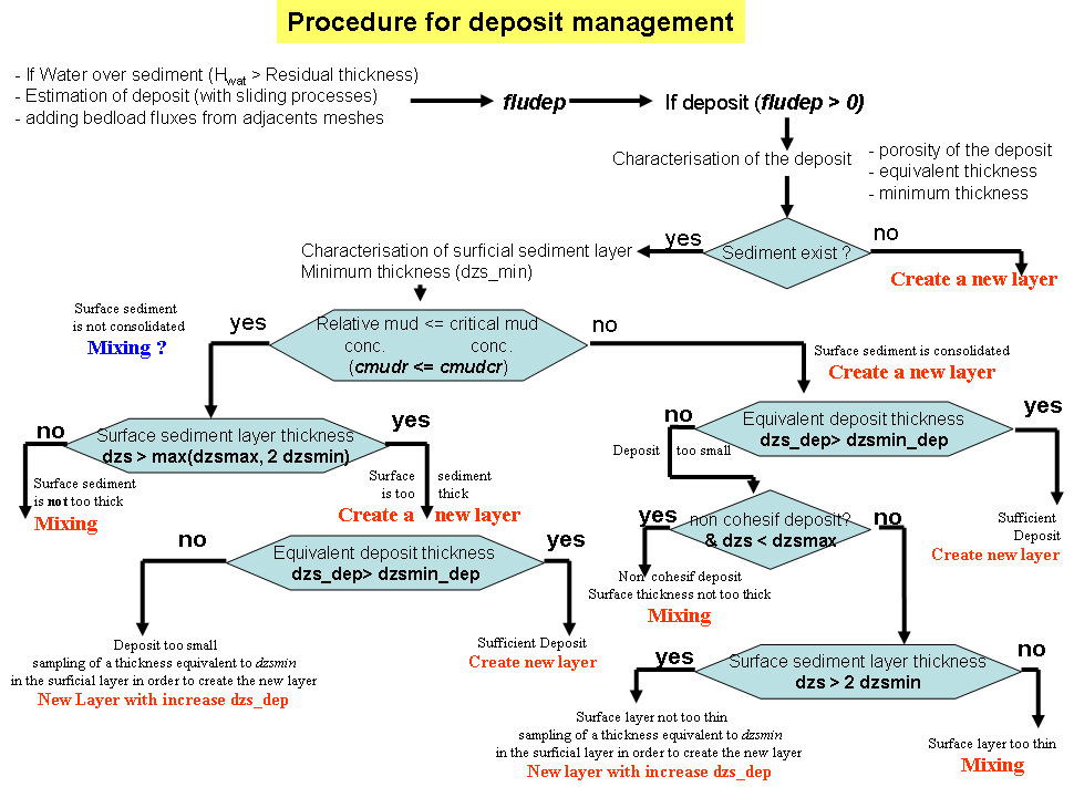
General procedure
- Step 1: Characterization of the deposit
- If the total deposit flow is non-zero, then the first step is to characterize this deposit in terms of :
- the composition (fraction and mass associated with each class),
- the porosity (new calculation method),
- the equivalent thickness of the deposit
- the minimum thickness of the deposit, given its composition.
- The mud is always deposited at a concentration called “fresh deposit”, that is to say, very little consolidated (cfreshmud parameter in kg/m3 to be entered in the paraMUSTANGV2.txt).
- Step 2: Characterization of existing sediment
- If the existing sediment contains at least one layer, the second step is to determine whether the deposit should be mixed with the existing sediment or whether a new layer must be created.
- In the same way as for the sediment to be deposited, the surface layer of the existing surface sediment is examined in terms of composition (relative mud concentration, state of consolidation, fractions of the different classes), porosity, thickness and minimum thickness related to its composition.
- Step 3: mixing with the surface layer or new layer creation
- Depending on the contrasts between the sediments to be deposited and those contained in the surface layer, the deposits will be mixed or not with the superficial layer.
- In some cases, if the new layer created from a deposit is not significant from the point of view of its equivalent thickness, this deposit will be thickened by removing part of the existing surface layer to create a new layer.
- how the deposit will be managed depends on several criteria, according to the following procedure:
- Step 4: finalization of the deposit
- If the result of step 3 is MIXING
- The mud relative concentration representative of the fusion between the deposit and the existing layer is calculated by reasoning in proportion to the mud masses (as a function of the parameter poro_option).
- The masses of each sediment class associated with the deposit and the surface layer are added and the “post-deposition” characteristics of the surface layer (thickness, concentrations) are updated by means of a new porosity calculation taking into account of the new composition of the mixture.
- If the result of step 3 is CREATE NEW LAYER
- A new layer is created respecting the characteristics of the sediment to be deposited
- In the case where the deposit is considered to be too thin, a part of the existing surface layer is removed (at its minimum thickness, dzmsina) to come densify and thicken the deposit.
- To do this, the characteristics of the deposit are updated before creating the layer including the portion of the layer ksmax from thickening.
- The mud relative concentration representative of the mixture between the deposit and the existing layer is calculated by reasoning in proportion to the mud masses (as a function of the parameter poro_option).
- Finally, a new porosity calculation makes it possible to update the thickness of the new layer to deposit.
- Step 5: fusion of the bottom layers if the maximum number of sediment layers is reached
- when the thickness of the layer located at the bottom of the sediment compartment reaches a certain thickness (dzsmax_bottom given in paraMUSTANGV2.txt) at the end of n merging phases, then it is the layer above which will then be thickened if new mergers involved.
- However, a certain number of surface layers (nlayer_surf_sed given in paraMUSTANGV2.txt) can not be melted and their maximum thickness remains always of the order of dzsmax.
- For bottom layers, dzsmax_bottom can be automatically expanded to satisfy the nlayer_surf_sed criterion.
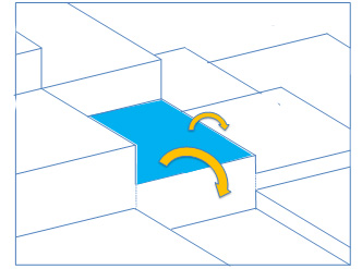
Sliding Processes
- A sliding process of the fluid mud was introduced into the model; mud slides if the slope is steep and deposits towards lower neighboring cells according to the slope